607 Results
View results:
Sort by:
Question
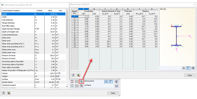
I have idealized a taper using a start and end cross-section (calculated in SHAPE‑THIN) and calculated a frame. During the stress calculation in STEEL, the error message "Tapered member contains incompatible cross-sections" appears. What is the error?
Question
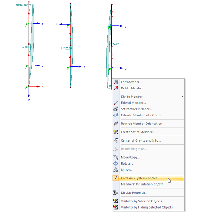
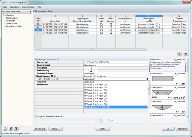
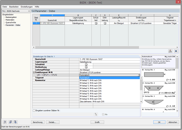
Why are there differences when calculating the elastic critical moment for lateral-torsional buckling Mcr according to DIN 18800 and Eurocode 3?